

Press Brake Tooling Selection Guide
How to Choose a Press Brake Upper Punch
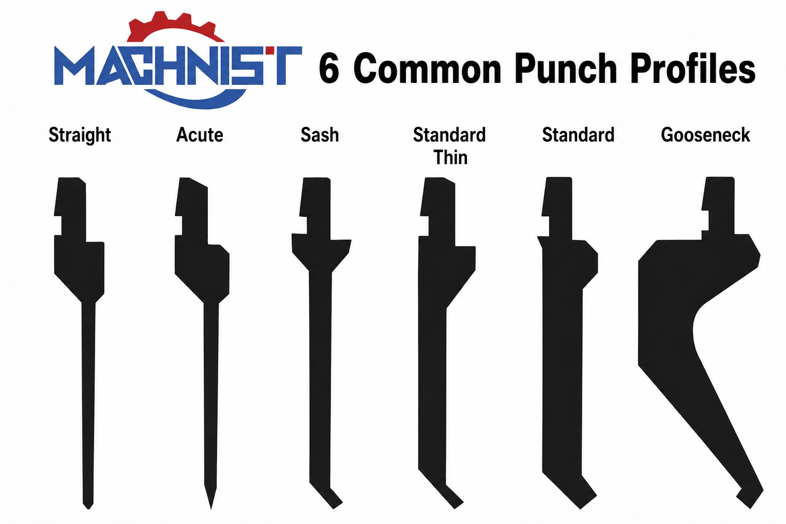
Compare six common upper punch profiles for acute bends, standard forming, frame profiles, return flanges and deep U-shaped parts. Select tooling according to geometry, clearance, forming load and the actual bending sequence.
Start with the Workpiece
Select an Upper Punch by Geometry, Clearance and Load
A press brake punch should not be selected by sheet thickness or bend angle alone. The correct punch must form the required geometry, avoid interference with previously bent flanges, and safely withstand the required forming force.
Part Geometry
Determine whether the part is a sharp edge, simple L-bend, frame profile, shallow channel, U-channel or deep enclosure component.
Clearance Requirement
Check whether a completed first bend will contact the punch body during the second or later bending operation.
Forming Capacity
Confirm the selected upper punch, lower die and press brake can safely carry the required bending force.
Core rule: choose the smallest punch profile that provides sufficient clearance for the complete bending sequence while meeting the required load capacity.
| Workpiece Requirement | Initial Upper Punch Direction |
|---|---|
| Sharp angle or pre-bending before hemming | A – 30° Acute Punch |
| Standard open bending with no flange interference | E – Straight Punch |
| Frame profile or returned edge needing localized clearance | D – Sash Punch |
| Shallow return bend or small channel | C – Small Gooseneck Punch |
| Typical U-channel or return-flange work | B – Gooseneck Punch |
| Deep U-shaped part or large return flange | F – Large Gooseneck Punch |
Sharp-Angle Forming and Hemming Preparation
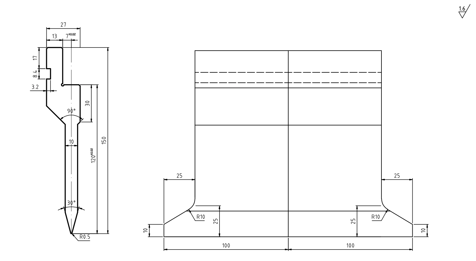
30° Acute Punch
Designed for acute-angle bends and preliminary folding operations where a narrow punch tip is required before hemming or final edge closing.
When Should You Choose It?
A 30° acute punch is used when the part requires a sharper preliminary bend than a standard 90° tool can produce. It is particularly useful for creating the first-stage acute bend before the material edge is flattened in a hemming operation.
- Acute-angle bending and narrow-tip forming.
- Pre-bending before hemming or edge folding.
- Finished edges on doors, covers and sheet panels.
- Suitable only after load capacity and acute die selection are confirmed.
 Real Tool Photo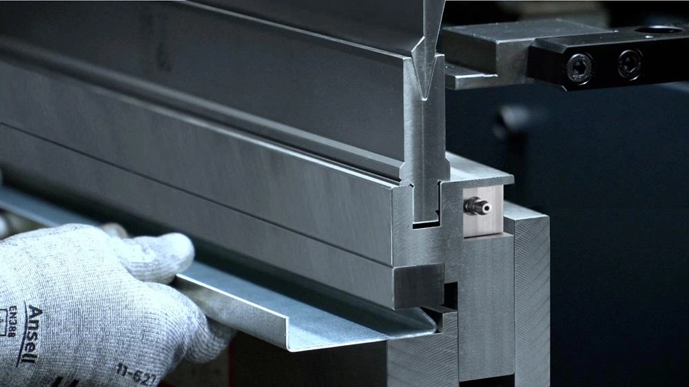
Real Application Case
Hemmed Door Edge or Protective Panel Edge
For an electrical cabinet door or stainless-steel cover, an exposed edge may need to be folded to improve stiffness and reduce sharp handling surfaces. The 30° acute punch first forms the narrow preliminary bend. A subsequent hemming operation completes the closed edge.
Selection tip: choose the acute punch for sharp preliminary folds or hemming preparation, not as the default tool for ordinary open 90° bends.
General-Purpose Standard Bending
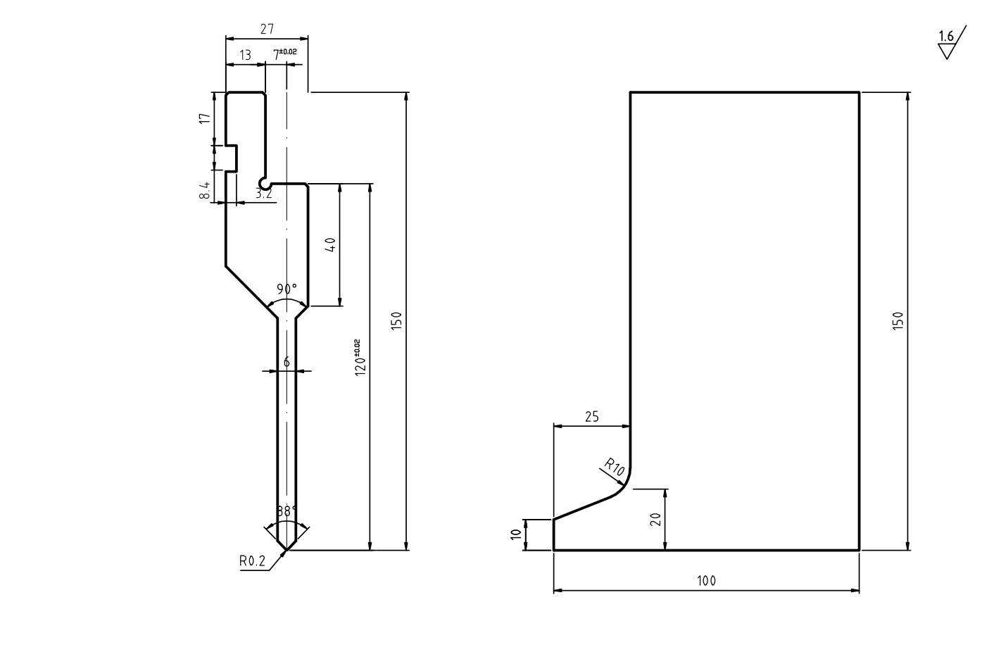
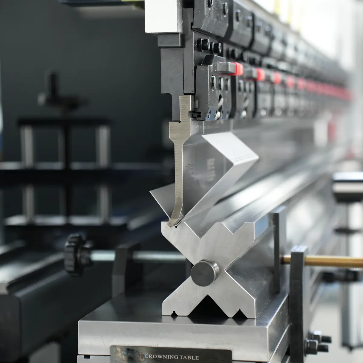
Straight Punch
A practical standard upper punch for open bending jobs where the workpiece can approach the tool without interference from formed sides or return flanges.
 Real Tool Photo
When Should You Choose It?
The straight punch is normally the first tool considered for ordinary air bending. Its compact structure is suitable for basic L-bends, open-angle profiles and parts that do not require relief clearance behind the punch.
- General-purpose open bending operations.
- Standard 90° brackets and machine panels.
- Applications where formed flanges do not collide with the upper tool.
- A strong and simple tool direction for routine production.
Real Application Case
Standard L-Shaped Mounting Bracket
A machinery manufacturer produces mounting brackets with a single 90° bend and no interfering return edge. A straight punch provides a simple, stable tooling solution for repetitive bending of standard parts.
Selection tip: a 90° bend does not automatically mean a straight punch is suitable. For second bends on channels or returned edges, verify clearance first.
Frame Profiles and Returned Edges
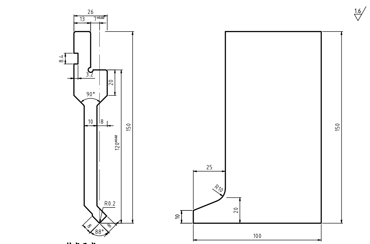
Sash Punch
A relieved upper punch profile used for frame-forming and returned-edge components where an ordinary straight punch does not provide sufficient localized clearance.
When Should You Choose It?
A sash punch is suitable for frame-type cross-sections, enclosure edges and returned profiles that require clearance near the bending area during later forming operations. It is especially relevant where the geometry resembles a door frame or formed sash profile.
- Metal door and window frame profiles.
- Returned sheet-metal edges and enclosure frame members.
- Parts needing more clearance than a straight punch.
- Moderate frame-related relief rather than very deep channel clearance.
 Real Tool Photo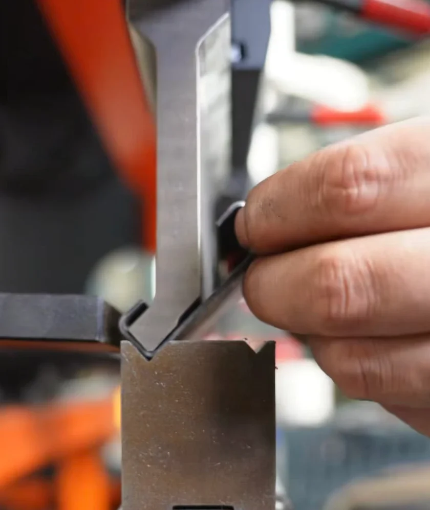
Real Application Case
Returned Metal Equipment Door Frame
A fabricated door frame requires several bends, including a returned edge that reinforces the profile and provides an installation surface. Once the first flange is formed, the sash punch gives the profile the extra working space needed for subsequent bending.
Selection tip: use a sash punch when the actual section contains a frame return or local obstruction; do not select it only because the customer works in a frame-related industry.
Shallow Return Bends and Small Channels
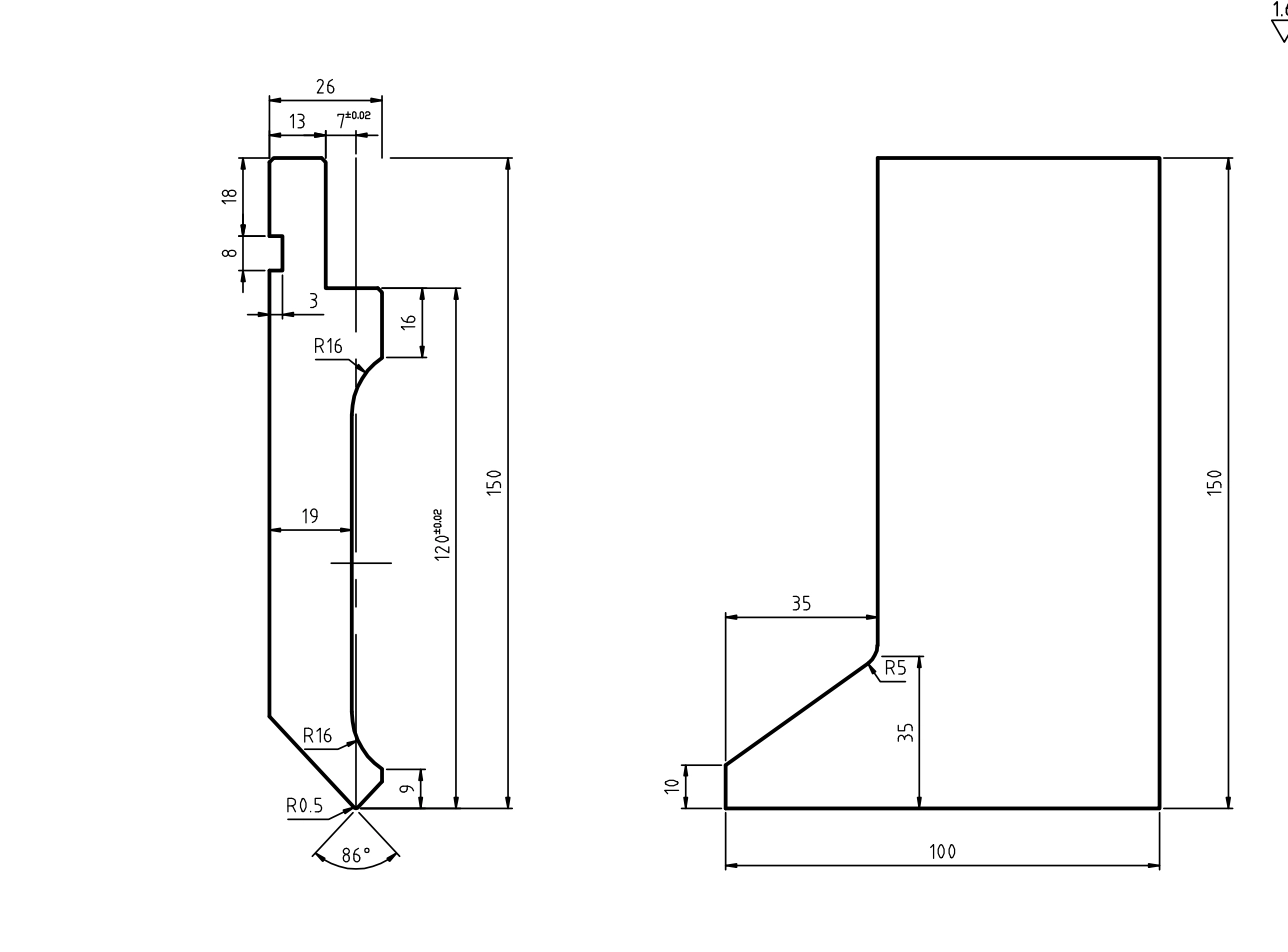
Small Gooseneck Punch
A compact relief punch that provides additional clearance for shallow channel or return-flange parts without using an unnecessarily deep gooseneck profile.
 Real Tool Photo
When Should You Choose It?
A small gooseneck punch is appropriate when a previously bent short flange would approach a straight punch, but the product does not require deep clearance. It provides a practical balance between relief capability and a relatively compact tool structure.
- Small U-sections and shallow trays.
- Short return flanges on light enclosure parts.
- Parts requiring limited but necessary punch clearance.
- A practical alternative before selecting a deeper gooseneck tool.
Real Application Case
Shallow Electrical Cover Channel
A small sheet-metal cover has two short side walls. During the second bend, the first formed side would come close to a straight punch. A small gooseneck punch provides sufficient relief without using a larger, deeper-clearance tool.
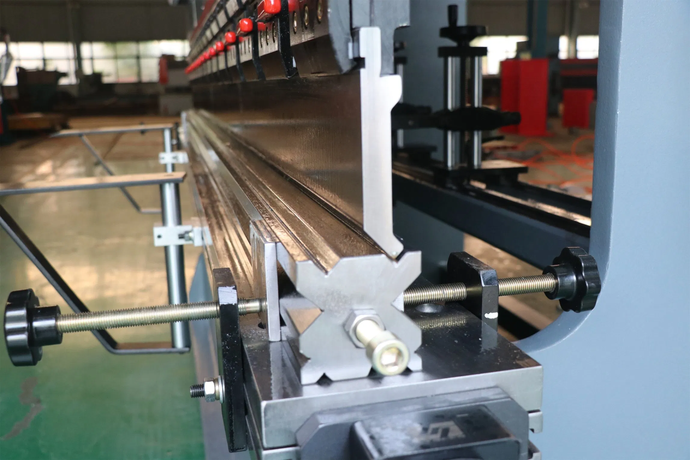
Selection tip: choose the smallest gooseneck profile that clears the part safely. Greater relief is not automatically better for every application.
U-Channels and Return-Flange Components
Gooseneck Punch
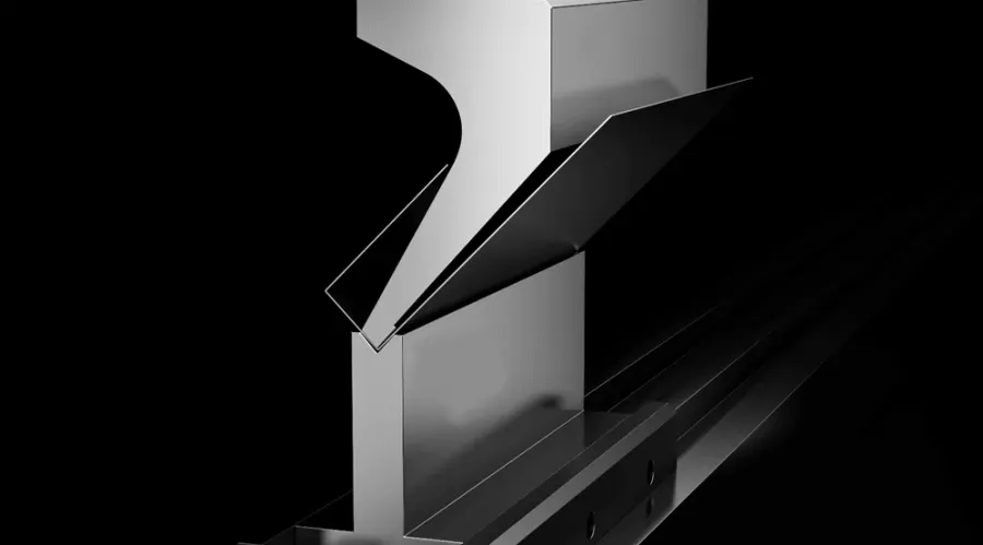
A common relieved upper punch for forming U-shaped components, channels and parts whose already bent flange would interfere with a straight punch.
When Should You Choose It?
The gooseneck punch is one of the most important tools for multi-bend sheet-metal components. Its recessed profile creates space behind the punch tip so that a formed side wall or return flange can pass without contacting the upper tool during a later bend.
- U-channel components and tray sections.
- Returned edges on cabinets and protective covers.
- Cable tray or housing parts requiring multiple bends.
- Parts where a standard straight punch causes interference.
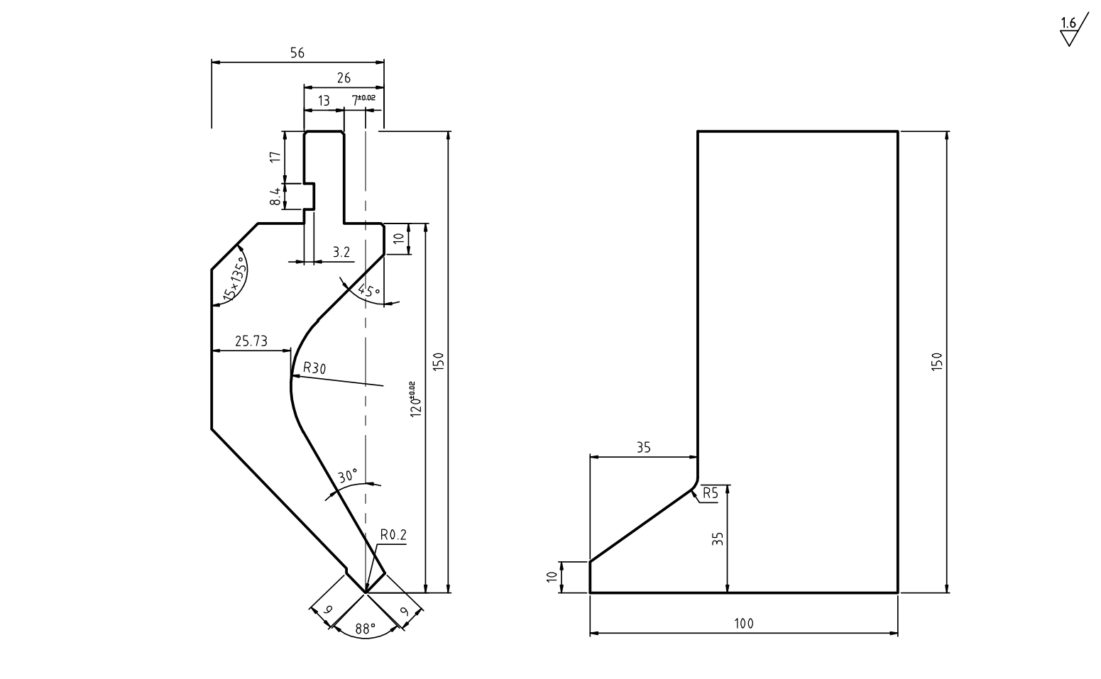 Real Tool Photo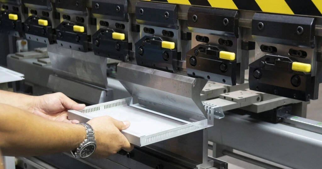
Real Application Case
Cable Tray Side Channel
A cable tray section requires two vertical sides and may also include returned edges. After the first wall is formed, it occupies the space near the upper tool during the next bend. A gooseneck punch creates the relief needed to complete the channel-forming sequence.
Selection tip: a gooseneck punch addresses common flange interference, but deep parts still require collision verification against the tool profile and machine working space.
Deep Parts and Maximum Relief Clearance
Large Gooseneck Punch
A deep-relief upper punch profile for workpieces with high side walls, deep return flanges or large U-shaped geometries that cannot be cleared by a standard gooseneck tool.
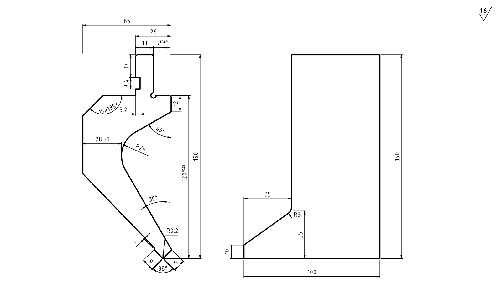 Real Tool Photo
When Should You Choose It?
A large gooseneck punch should be considered when an ordinary gooseneck still does not provide enough working space for a completed flange or vertical wall. It gives greater clearance during the second or later bend of deep components.
- Deep U-shaped channels and large box panels.
- High return flanges or tall already-formed side walls.
- Large enclosures and heavy machinery covers.
- Applications requiring full collision and tooling-load confirmation.
Real Application Case
Deep U-Shaped Machine Protection Cover
A large protection cover has deep side walls. During the second bend, the already formed wall would collide with a straight punch or ordinary shallow-relief tool. A large gooseneck punch is the initial solution direction, subject to verification of punch load, stroke, open height and the complete bending sequence.
Selection tip: large clearance does not remove the need for engineering verification. Deep-relief tooling must be checked together with press brake tonnage, open height, stroke and collision risk.
Quick Comparison
Which Press Brake Upper Punch Fits Your Part?
| Upper Punch | Clearance Level | Typical Parts | Main Advantage | Key Check Before Selection |
|---|---|---|---|---|
| A – 30° Acute Punch | Low | Acute folds, hemmed edges | Forms sharp preliminary bends | Acute die, tip load and hemming process |
| E – Straight Punch | Low | L-brackets, panels | Simple, stable standard bending | No interference on later bends |
| D – Sash Punch | Medium | Frames, returned edges | Localized frame-profile clearance | Cross-section and return geometry |
| C – Small Gooseneck | Medium | Shallow channels, small trays | Moderate relief in compact form | Required flange clearance |
| B – Gooseneck Punch | High | U-channels, cable trays | Common return-flange relief | Bending sequence and interference |
| F – Large Gooseneck | Very High | Deep covers, large enclosures | Greater clearance for deep parts | Load, stroke, open height and collision |
Selection Process
Four Steps to Confirm a Suitable Upper Punch
Review the Part Section
Identify the bend angle, flange height, channel depth and any returned features.
Check Clearance Risk
Determine whether a previously formed side may contact the punch during later bends.
Match the Lower Die
Select the V-opening together with material, thickness, radius and minimum flange needs.
Verify Force and Collision
Confirm tool load, press brake capacity and the full bending sequence before production.
Send Us Your Part Details
Information Required for a Reliable Tooling Recommendation
For ordinary parts, a clear dimensional drawing may be enough for an initial selection. For return flanges, U-shaped channels and deep enclosures, DXF or STEP files are strongly recommended for clearance evaluation.
Real Tooling and Bending Proof
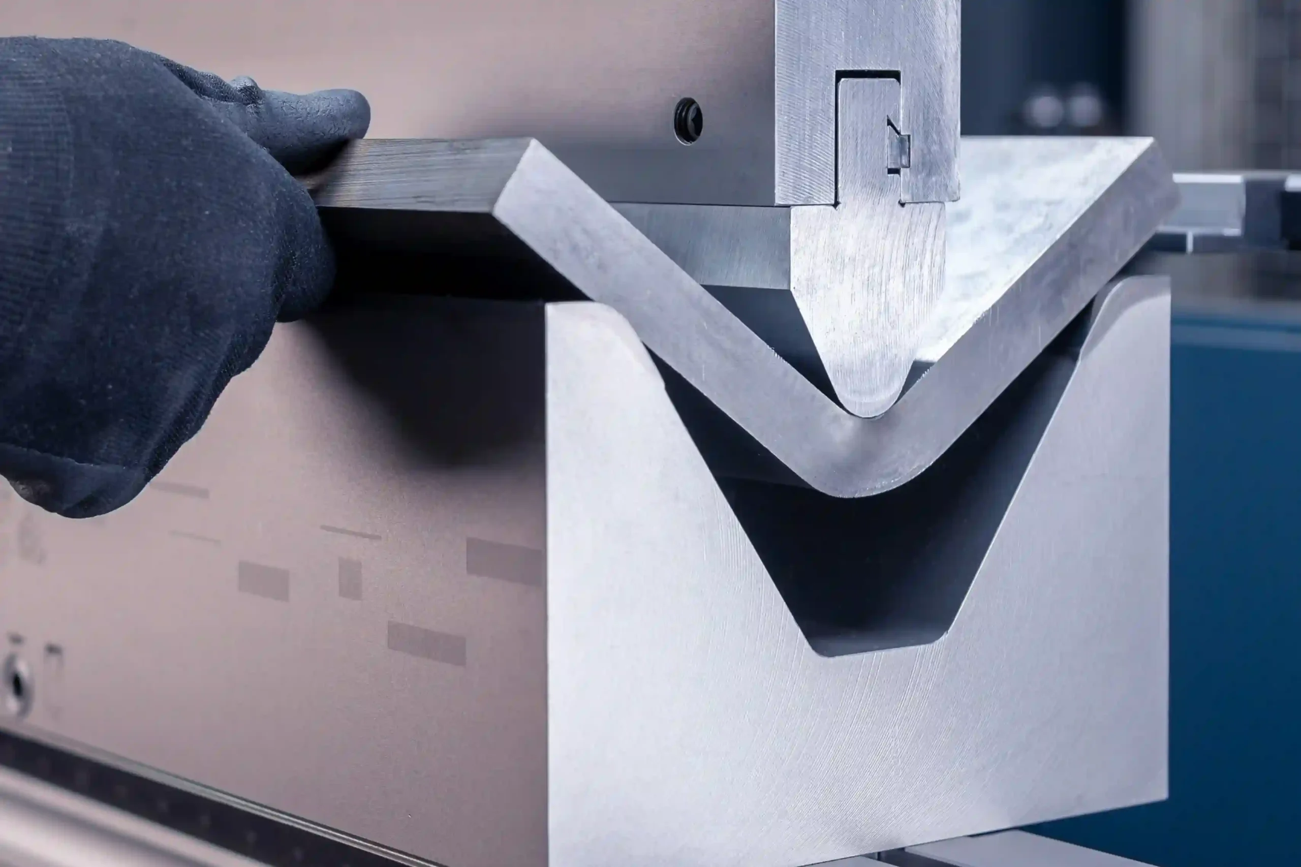
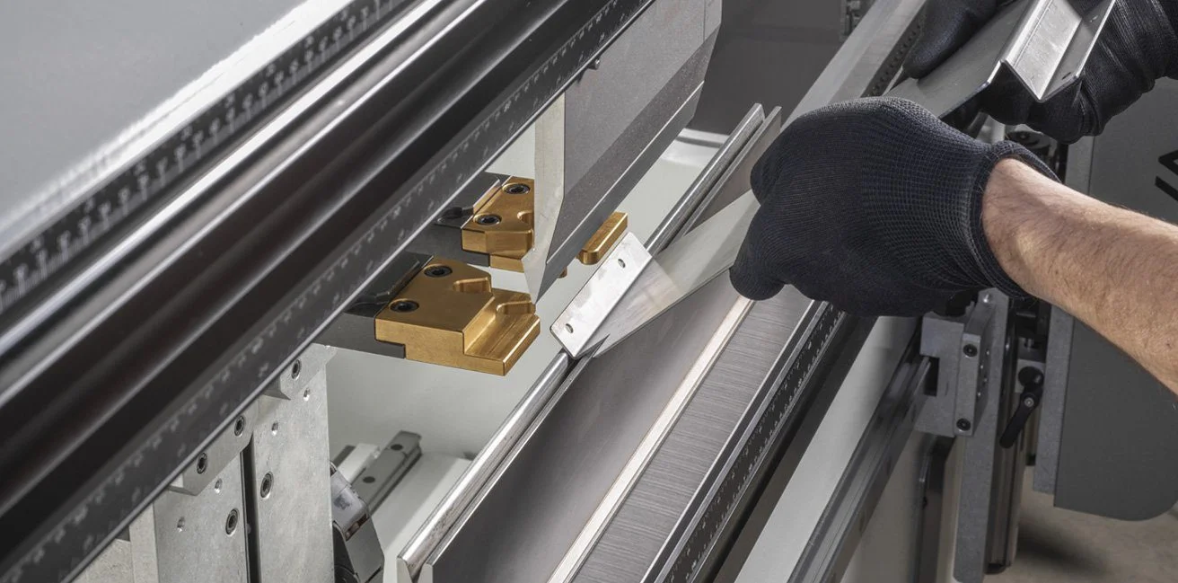
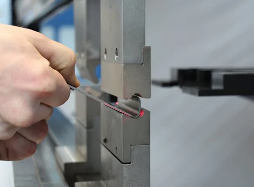
MACHNIST Tooling in Actual Production
Add additional factory photographs here when available: tooling installed on the press brake, finished workpieces and bending-process views. These images support customer confidence beyond schematic explanations.
Not Sure Which Press Brake Punch Fits Your Parts?
Send us your workpiece drawing, material, thickness and bend length. MACHNIST will help evaluate the suitable upper punch, matching lower die and press brake configuration for your bending application.